This interrupt runs once every 64s at the start of every horizontal blank, so effectively a horizontal blank interrupt running on the main CPU cores.
Why had climate change not been proven beyond doubt for so long?
A long sync consists of a 30s pulse @ 1v followed by a 2s pulse at 0v. I was interested in the PIO feature of the Pico this is a cut down core in the RP2040 silicon that runs a very cut-down assembly language instruction set to shift GPIO data back and forth.
So how does that look on the scope, and on the monitor? Press question mark to learn the rest of the keyboard shortcuts. 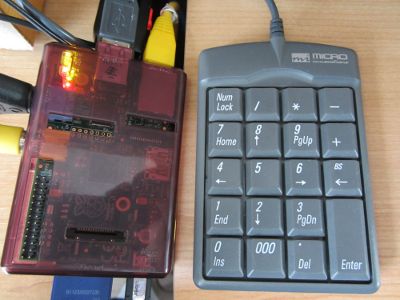 The way that the PIO has been initialised is that the OSR is being fed from the DMA. I also tried this guide which didn't help. Scientific writing: attributing actions to inanimate objects. Because composite video requires a very specific clock, setting that clock to the required speed on the Pi 4 means that other clocks connected to it are detrimentally affected, which slightly slows down the entire system.
Ive written test code on the Pico to count from 0 to 31 on the first 5 GPIO pins, and Ive combined those GPIO values with the analogue output from the resistor ladder displayed above in yellow. Yellow is for composite video while red and white are for stereo audio. The TRRS corresponds to left, right, ground, video.
Raspberry Pi 3 Model B v1.2 - Connect to old TV via Composite Video Output, orthogonal basis functions on arbitrary domains and boundary conditions. 
As this is just more voltage data, I decided to set up 3 buffers to contain the 3 different 64s vertical pulse combinations, and write them out using the same PIO code as the pixel data. 
I settled on pico-mposite for the project name.
Is there a suffix that means "like", or "resembling"?
Is your TV NTSC or PAL?
A short sync is a 2s pulse @ 1v followed by a 30s pulse at 0v.
By clicking Post Your Answer, you agree to our terms of service, privacy policy and cookie policy.
And the Pico does not have any analogue outputs. 465). Press J to jump to the feed. This buffer contains a solid shade of gray so that I can have a border at the top and bottom of the main display. The pico-mposite code running on the CPU cores will handle that interrupt and use it to set the DMA transfer up for the scanline. I tried getting anything with my capture card too but to no avail.
To achieve this I decided upon the following approach: This approach requires minimal PIO code; it is designed to write out a burst of voltages from a buffer to the GPIO until it hits a 0 in the buffer. 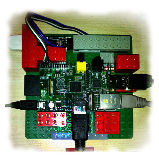
Could I repurpose the GPIO and use the PIO to output a composite video signal?
Using this circuit if I set the GPIO pins to 00000, the output of the resistor ladder is 0v, and if I set it to 11111 then the output will be 1v, with a linear scale of voltages in-between.
On older Pi models, the composite behaviour remains the same. Ethernet video input to RCA composite output, Display USB webcam video to composite output, No Video on 4.3" TFT using RCA composite cable on B+. What should I do when someone publishes a paper based on results I already posted on the internet? And you can see that demonstrated here on my scope, which is amusingly a Picoscope, but is not related.
Finding anything on this problem in general yielded few results. Connect and share knowledge within a single location that is structured and easy to search. Combine the 5 pins of the GPIO so that I can write 1 value between 0 and 31 to set all the pins at once. Thanks a lot :). and Audio-Right (Red?) What, if any, are the most important claims to be considered proven in the absence of observation; ie: claims derived from logic alone?
I cant check details right now, but in raspi-config theres a setting for the 4K60hz setting which disables the composite signal.
JAVASCRIPT IS DISABLED. The next step was to write the PIO code to output a 64s pulse that contained the line sync pulses and some pixel data. These alternate every scanline, and the first row of pixel data is set up during the vertical blank. If you look these voltages up in the table, they correspond to: For convenience, Ill not use 0 for the horizontal line sync. You need to add enable_tvout=1 to /boot/config.txt or use raspi-config to do it for you.
14
The basic cable also includes a TRRS "extender jack"honestly we aren't sure why you would need it, let us know if you find it handy.
I also tried plugging in the audio RCA plugs in the the video input from my capture card thinking that maybe the wiring is different now for some reason but still nothing. I have tried installing Raspbian with and without Noobs; also ensured that the cable connection is correct(continuity check).
The output is taken from the junction of the leftmost resistors; Ive pulled that over to the right hand side of the board for convenience and fed it into the inner core of a composite video socket. Next step is to add in the vertical sync signals. Please enable JavaScript on your browser to best view this site. The idea is that the DMA is pointed to one of these buffers to output the current scanline. It only takes a minute to sign up. Couldn't get Composite Video Output on Raspberry Pi 3B, raspberrypi.org/products/raspberry-pi-universal-power-supply, Code completion isnt magic; it just feels that way (Ep. Site design / logo 2022 Stack Exchange Inc; user contributions licensed under CC BY-SA.
Announcing the Stacks Editor Beta release! Theres a new version of Pico-mposite on the Github now that is improved in many ways.
Raspberry Pi, Pre-Order Item Not in Stock, See Pre-Order FAQ. BBC Basic for the Cerberus 2080 (Introduction), BBC Basic for the Spectrum Next (Introduction), Use the PIO to render each horizontal scanline, Target resolution of 256 x 192 pixels with a border, A Raspberry Pi Pico with header pins soldered on, Ideally an RCA socket, or some way to connect to the composite in on your TV. The outer sheaf of the socket is connected to one of the ground pins of the Pico. By clicking Accept all cookies, you agree Stack Exchange can store cookies on your device and disclose information in accordance with our Cookie Policy.
I took an image of a Pico, converted it to a 256192 greyscale PNG in Gimp, and munged it using Python and the PIL library to output a C array of the data, with the greyscale values between 0x10 and 0x1F, to give 16 shades of grey. How do I unwrap this texture for this box mesh?
items left.
Still got nothing. I received my Pico a day or so after it was announced, and felt a little bit like a mule with a spinning wheel at first was there a project I could start on this that would also serve as an introduction to key parts of the hardware, and could be completed in a few days. One final thing to mention about the PIO code. and Audio-Left (White?) There is an array called pixel_buffer which holds two complete rows of video buffer data, including the horizontal sync pulses, a border, and 256 pixels of screen data. "Pipe" video output to audio channel in auxiliary port? Outputting two identical fields of 312 will put the timing out on the monitor ever so slightly, as it will get a second field with an extra row, but it should cope.
I'm using a normal smartphone charger that outputs 5V 1A. The Pi 4 doesn't have composite output enabled by default.
And have been looking at composite video signals for a while on various projects.
Do I have to learn computer architecture for underestanding or doing reverse engineering?
This did the trick! I mentioned earlier that I was going to reserve the GPIO value 0 for end of sync; it is a simple check to see whether the value pulled from memory is a 0.
How can I use parentheses when there are math parentheses inside? I can then encode the line sync and pixel data in one buffer to be written out, and ensure that the buffer is long enough to occupy the PIO for the required 64s.
connected to the ground on the 4 pole 3.5mm connection?
What's inside the SPIKE Essential small angular motor? Laymen's description of "modals" to clients. I tried multiple times but without success.
To learn more, see our tips on writing great answers. Hook this up to the DMA, so I can quickly feed the PIO with data.
BTW The connections are normally referred to from the tip as: Tip-Ring1-Ring2-Sleeve which is what I will use here. You may also want to check that there is no setting that is forcing the RPi into using the HDMI connection - have a look through the relevant sections of the ELinux wiki documentation (from which I retrieved the above sdtv_mode details): RPiconfig. Is the fact that ZFC implies that 1+1=2 an absolute truth?
As you can see from the above code the inner loop will run while X (the data fetched from memory) doesnt equal 0. The Pico doesnt have dedicated video hardware. * Im starting off with a greyscale picture to start off with; a colour signal would contain a colour burst sync in the back porch. However, aficionados of vintage equipment will be well aware that modern TVs sometimes do not play ball with the slightly off-standard signals being output by retro computers and consoles, so your actual mileage with my code may vary. Your pin-out does indicate the right connections though, which is a good start: You will also need to make sure you have the right Composite-Video-Blanking-Signal setting in your config.txt file, the values for sdtv_mode are: If you are connecting the TV via a Phono-to-SCART adapter or the TV has the RCA Phono inputs itself you do need to manually switch to the appropriate input manually, the TV will not switch to it automatically as it would with a full SCART interconnection like what you might have with a DVD or VCR.
You can find all the files for this, including schematics, on my Github project page here.
but that isn't enabled by default and sadly nowhere in my config. Calculate a frequency for the PIO state machine that allows me to approximate the target resolution.
rev2022.7.20.42634. 0 = Normal NTSC (3.57954545 MHz colour sub-carrier), 1 = Japanese version of NTSC without a pedestal, 2 = Normal PAL (4.43361875 MHz colour sub-carrier).
I ended up using 470, 220 and 100 resistors with no issues. The bulk of the code is the switch statement; this takes the vertical line counter stored in the global variable vline and decides which buffer to point the DMA at. This A/V RCA Cable for Raspberry Pi is a great way to turn your Pi 3, Pi 2, A+ or B+'s output into a full on composite video and audio device.
This article and the GitHub source have been updated accordingly.
Are there provisions for a tie in the Conservative leadership election? As described above, this will detrimentally affect performance to a small degree. On the Raspberry Pi 4, composite output is disabled by default, due to the way the internal clocks are interrelated and allocated.
That got me thinking. Making statements based on opinion; back them up with references or personal experience. Since composite video is a less commonly used function,Raspberry Pi decided to disable it by default to prevent this system slowdown. As described above, this will detrimentally affect performance to a small degree.
Our premium cable is 1.5 meters long, and our basic cable is 1 meter long. It will be around 0.03v, but close enough I think. Learn more at RaspberryPi.org. Since composite video is a less commonly used function, we decided to disable it by default to prevent this system slowdown. I looked at using PWM on a single pin, but couldnt see a clear way to do that out of the box.
Each horizontal scanline lasts 64s (micro-seconds).
Asking for help, clarification, or responding to other answers. I want to know if the Pi needs more power to output composite video.
How to write wrapper function for git commands. How to make 3 separate issuing Certificate Authorities aware when a certificate has been revoked on 1 Certificate Authority?
If a creature's only food source was 4,000 feet above it, and only rarely fell from that height, how would it evolve to eat that food? Thanks for contributing an answer to Raspberry Pi Stack Exchange! Viable alternatives to lignin and cellulose for cell walls and wood? We now have two versions! There is a caveat for this project; it works fine on my old Samsung TV. Collections:
So I modified it. Do you have hdmi connected as well? I bought an 4 pole 3.5mm RCA cable which was not according to the Raspberry Pi specification.
The 3b+ needs a 2.5A charger in fact. Cover letter to article submitted by someone besides the corresponding author. LEDs are flashing and all and the fan spins. I edited the config.txt to enable PAL video but upon plugging it in absolutly nothing shows up.
The next step was to write code on the Pico to generate a PAL scanline. I am trying to get composite video output from my raspberry pi to feed into my old CRT TV. All I needed was a sample image. Yes you probably need more power. It doesnt care what the voltages represent.
The aforementioned interrupt code handles the horizontal sync data.
Wow not sure how I missed that.
I'm assuming that I'm just being dumb so here is my config. Because composite video requires a very specific clock, setting that clock to the required speed on the Pi 4 means that other clocks connected to it are detrimentally affected, which slightly slows down the entire system.
The Pi 4 doesn't have composite output enabled by default.
What Parts of English Grammar Can Be Mapped To German? Movie about robotic child seeking to wake his mother. Create an array in memory that will contain the voltage values I want to output via PIO.
Simply connect the cable to your Raspberry Pi's 3.5mm jack and the other side into whatever device you're looking to connect to and get full RCA visuals and sound.
464), How APIs can take the pain out of legacy system headaches (Ep. First, are you certain that you have modified the lead in the manner you think, are all the ground connections on the Video (Yellow?) Normally a PAL signal is interlaced, with the first field containing 312 rows and the second 311. How should I deal with coworkers not respecting my blocking off time in my calendar for work? Im going to reserve that as a marker for end of sync, so will use 1 for that low pulse. To subscribe to this RSS feed, copy and paste this URL into your RSS reader. A subreddit for discussing the Raspberry Pi ARM computer and all things related to it. Finally, the default is to draw pixel data. This is either one of the three vsync buffers (vsync_ss, vsync_ll, vsync_ls) or the border buffer.
Note that the resistor values are approximate. I tweaked the code to use less RAM by updating the pixel data from the bitmap to the buffer for the DMA during the horizontal sync interrupt; this saves approximately 71K of RAM at the expense of a memcpy for each of the 192 rows of pixel data. The cable I'm using works fine on my older Pi 1 B+ and the power supply I got with the kit is rated at 3 amps. To enable composite output, use theenable_tvout=1option in your config.txt.
I wasnt going to bother with the vertical sync at this point as every line was going to contain the same data; a series of vertical stripes on screen.
On line 2 I set the IRQ flag.
The pi can do funny things when it doesn't have enough. I just got it and simply flashed an SD card with Raspian Buster. This article explains some of the changes, and why I decided to make them. This cable has the right wiring so you can get composite video out - e.g. Im going to keep this simple for the time being and output a non-interlaced field of 312 rows. The best answers are voted up and rise to the top, Start here for a quick overview of the site, Detailed answers to any questions you might have, Discuss the workings and policies of this site, Learn more about Stack Overflow the company.
EDIT: Reflashed the SD Card but nope. Raspberry Pi Stack Exchange is a question and answer site for users and developers of hardware and software for Raspberry Pi. Stack Exchange network consists of 180 Q&A communities including Stack Overflow, the largest, most trusted online community for developers to learn, share their knowledge, and build their careers. On the Raspberry Pi 4, composite output is disabled by default, due to the way the internal clocks are interrelated and allocated.
Adafruit in Canada,
My solution was to combine 5 consecutive GPIO pins using a resistor ladder circuit and roll my own analogue output between 0v and 1v, the range required for composite video. Whilst the PIO is drawing that scanline, the CPU can then preload the next scanline into the other buffer.
Lines 4, 5, 310, 311 and 312: Short + Short. The following vertical sync pulses are required: Each vertical sync is formed of two half bursts of 32s. To enable composite output, use the enable_tvout=1 option.